PCBs for this project have been discontinued.
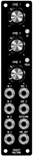
The suggested panel design for the MOTM format Multimix.
A highly useful utility module. It's a four channel mixer with a twist. The first three inputs have each an independant level control. Each level control can be set so that the gain of the input is anything from -1.1 to +1.1. This means that not only can inputs be added together, but can subtract as well. With each input knob set to its middle position, then none or very little of the input signal will reach the output.
Mixers with reversible attenuators on their inputs are very useful for controlling audio and CVs. One excellent application uses a MultiMix with a VCA to create a very flexible ring modulator.
The Multimix also features a fourth input. Whatever signal is connected here is summed with the final mixed output. This can be used to cascade several Multimixes together to form much larger mixers.
The module features a clever combination of four output sockets to achieve a variety of uses. Two mix outputs are available: One is MIX OUT and this is simply the four inputs added together - the first three inputs being added according to the levels set by the pots. The second main output is OUT3/MIX. This is exactly the same as MIX OUT until you start connecting jack plugs to either OUT1 and/or OUT2.
Inserting a jack into OUT1 and the IN1 signal will be removed from the OUT3/MIX socket. It will, however, still be present at the MIX OUT socket. The OUT1 socket gives you only that pot controlled version of the signal going into IN1. As before the pot will control the level and phase of the signal. You can thus use this pot to attenuate, or invert, CV or audio signals independantly of what is happening on the other three inputs. Inputs 2 and 3 also behave likewise. They can be treated as independant reversible attenuator channels or be treated as level controls on a mixer. It all depends on how those output sockets are used.
The module also features two output level LEDs. These monitor the signal level at the MIX OUT socket. The 5V one lights when the signal exceeds +/-5V. The peak one lights when the output signal is getting near clipping, ie. around +/-11V. Special circuitry is employed to ensure the LEDs do not cause power supply clicks when they turn on or off.
The input level pots can also be easily configured as ordinary level pots rather than reversible attenuators if desired.
Power (+/-15V) is provided to the board either by our standard Oakley/MOTM 4-way header or Synthesizers.com header. Current consumption is approximately 35mA per rail.
The Multimix issue 6 PCB size is 104mm (high) x 104mm (deep).
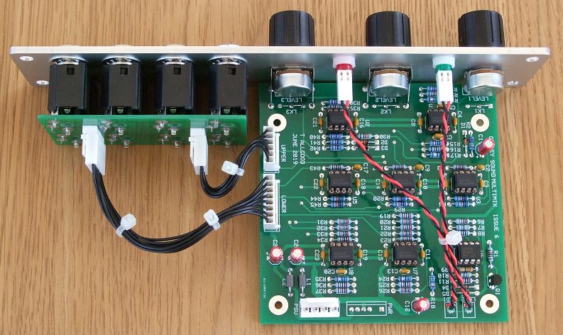
The Oakley Multimix issue 6 board behind a natural finish Schaeffer panel. Note the use of the optional Sock-8 board to make wiring the socket field much easier.
Project Downloads
Multimix issue 6 Builder's Guide
Multimix issue 5 Builder's Guide
Construction Guide Our handy guide to building Oakley DIY projects
Parts Guide Our handy guide to buying parts for Oakley DIY projects
Links to schematics are available to purchasers of the PCB or module and will be sent via e-mail when the board(s) are shipped.
Front Panel database
A Schaeffer front panel can be made for this module. The databases can be found by downloading the following links:
5U format filter core module in traditional black
5U format filter core module in natural silver
To read, edit and print this file you will need a copy of 'Frontplatten Designer' from Schaeffer. Panels can be ordered via Schaeffer's website.
Schaeffer are based in Berlin, Germany and can send panels to anywhere in the world. Delivery to the UK normally takes around ten days. For North American users you can order your Schaeffer panels from Front Panel Express.
Back home